DIY Simple Headphone Amp Tutorial
By Cmoy Design (Mini Pocket Amp)
.jpg) A step by step guide to build a headphone amplifier.
A step by step guide to build a headphone amplifier.
It sound wonder with Ipod.
By Cmoy Design (Mini Pocket Amp)
Cmoy amplifier is currently the most popular headphone amplifier for beginner to DIY. It only use a 9v battery to drive this headphone amplifier, and it sound excellent! The complete headphone amplifier it self is very small, you could pack the circuit board & battery into a candy tint which is portable to carry around with your ipod or any portable mp3 player. To diy this cmoy headphone amplifier is extremely easy and simple, it only take less then a day to complete.
.jpg) A step by step guide to build a headphone amplifier.
A step by step guide to build a headphone amplifier.It sound wonder with Ipod.
The Cmoy Headphone Amplifier Component Parts 1
The Cmoy Headphone Amplifier Component Parts 2
A Picture say a thousand words, As stated very clearly that what are the component needed for this Cmoy amplifier. Print and bring this out with you when you go to the radio shack to get this component.

The Cmoy Headphone Amplifier Component Parts 2

A Picture say a thousand words, As stated very clearly that what are the component needed for this Cmoy amplifier. Print and bring this out with you when you go to the radio shack to get this component.
Step 5
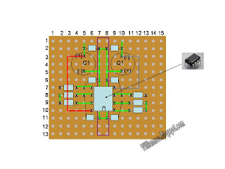
 As you can see on the picture above, the green line indicate that we have to solder and connect hole 4 to 5 to 6. On the other side we have to solder hole 9 to 10 to 11.
____________________________________
*NOTE: How to solder the green line?
 There are 2 type of joining the green line, for beginner I will suggest you to use type "A".
Type "B" need more stable hand but less of trouble to cut the left over wire from resistor or capacitor.
___________________________
Once you have done up to step 5, you should test your circuit by connect it to a 9v battery and toggle on the switch, the led should be lighted up. If you can't get the led to work, please go back to STEP 4, Reverse your Power Led connection and test again.
This is what you should have by now
 As you can see on the picture above, the green line indicate that we have to solder and connect hole 4 to 5 to 6. On the other side we have to solder hole 9 to 10 to 11.
____________________________________
*NOTE: How to solder the green line?
 There are 2 type of joining the green line, for beginner I will suggest you to use type "A".
Type "B" need more stable hand but less of trouble to cut the left over wire from resistor or capacitor.
___________________________
Once you have done up to step 5, you should test your circuit by connect it to a 9v battery and toggle on the switch, the led should be lighted up. If you can't get the led to work, please go back to STEP 4, Reverse your Power Led connection and test again.

This is what you should have by now
Step 6
Mount the (R1) 4.7k Ohm 1/4 w Resistor onto the board.
Solder the green line shown above.
Step 7
 Mount (C1) 220uF 16v Capacitor.
Solder the green line as shown above.
Step 8
Mount R2 Resistor.
Solder green as shown.

Mount the (R1) 4.7k Ohm 1/4 w Resistor onto the board.
Solder the green line shown above.
Step 7
 Mount (C1) 220uF 16v Capacitor.
 Solder the green line as shown above.
Step 8

Mount R2 Resistor.
Solder green as shown.
Step 15
 Slot the IC Chip into the socket. Compatible Chip are as follow:
Blurr Brown IC: OPA2227
Blurr Brown IC: OPA2132P
Blurr Brown IC: OPA2132PA
Blurr Brown IC: OPA2134PA
TL072We are almost done...
 Slot the IC Chip into the socket. Compatible Chip are as follow:
Blurr Brown IC: OPA2227
Blurr Brown IC: OPA2132P
Blurr Brown IC: OPA2132PA
Blurr Brown IC: OPA2134PA
TL072We are almost done...
To continue read more....


.jpg)